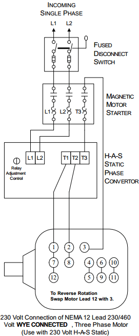
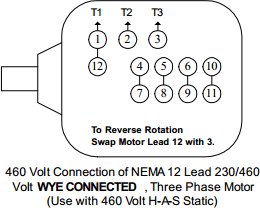
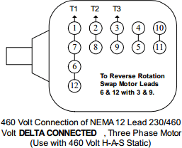
For models manufactured in 2000 or later
In the schematic diagram pictured, the H-A-S Static Converter is installed between the motor and the magnetic starter. The wiring diagrams on Page 5 show other correct types of installations for reversing applications. Carefully connect each wire as shown by the appropriate diagram. Any incorrect connections will result in unsatisfactory operation. NOTE: Do not expect three phase amperages values for T1, T2, or T3. See explanation of Operation on Page 6. See Page 4 for recommended heater coil, wire and system component sizing information.
The H-A-S Static Converter when connected properly, performs as an integral part of the motor. For this reason, the H-A-S Static Converter must be of the same HP rating as the motor. Do not use a smaller or larger HP rated H-A-S Static Converter than the HP rating of the motor used. A mismatch in size will result in unsatisfactory performance.
IMPORTANT: The Relay Adjustment Control is an adjustment for the relay which controls the starting cycle. This adjustment should be made when the motor is under the maximum starting load, (if done properly this adjustment should not be necessary again unless the motor is moved or the starting load is changed greatly). The adjustment is made as follows. Turn the control knob to the extreme right (clockwise), then start the motor. If the relay chatters, or pulls in too soon, turn the knob in a counter clockwise direction until the relay pulls in with a clean snap. The relay is adjusted properly when it pulls in just as the motor reaches its rated speed.
CAUTION: The starting capacitors must not remain in the circuit longer than 15 seconds. Damage may result if this limit is exceeded.


