Wye (Star) Connected Motor & Delta Connected Motor
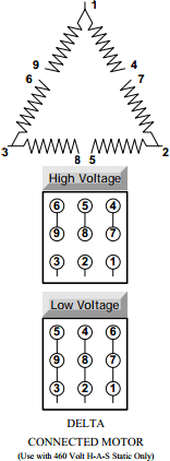
NOTE: Connection diagrams shown below are for motor type identification purposes only and are not to be used for connection of the H-A-S Static Phase Converters. Compare the connections below with those listed on the motor nameplate to identify whether the motor is a wye or delta wound motor.
EXCEPTION: Oil Field Pumping Unit Motor — The 12 lead, Triple Voltage (230/460/796) Oil Field Pumping Unit Motor may be used with the 460 Volt H-A-S Static without modification. However, this is a Delta connected motor and must be used on 480 Volt Single Phase.

CONSIDER THE 460 VOLT H-A-S STATIC ON LARGE MOTOR INSTALLATIONS:
A 460 Volt installation will require smaller service and can be used with either a wye (star) or delta connected motor.
CONSULT POWER SUPPLIER AS REGARDING AVAILABLE SERVICE:
Incoming service must match the phase converter being used. i.e. – When using a 460 Volt H-A-S Static, service must be 480/1/60, and when using a 230 Volt H-A-S Static, incoming service must be 240/1/60. The 230 Volt H-A-S Static will not operate on 208 Volt Service.
Motor Modifications
For a 230/460 Volt, Single Speed, 9 Lead, 3 Phase Motor
Wye (Star) Connected Motor
For Use With 230 & 460 Volt H-A-S Static Converter
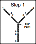
Step 1. After removing the rear end bell of the motor, the point in the winding that was formed by joining the three internal ends of the three phases together must be located. This point is commonly known as the “Star Point”, as indicated in the figure Step 1. It is readily identified by three wires or groups of wires in individual sleevings joined together electrically and mechanically inside the motor winding.
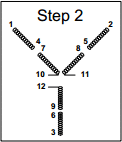
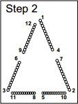
Step 2. After the Star Point is located, the three ends are then separated. The ends of the nine motor leads are also separated, so that no two ends are touching (for testing purposes). Care must be exercised when two and four circuit windings are encountered, as these sometimes have more than three ends joined together to form the Star Point. All ends must be separated.
By using an ohmmeter or test light, the Star Point end or ends, that show continuity to motor lead #7 should be located and a length of motor lead wire attached to this end, or ends, and permanently marked as motor lead #10. The end of # 8 should be located, and a lead wire attached (in the same manner) and permanently marked as motor lead #11. The end of #9 should be located and a lead wire attached (in the same manner) and permanently marked as motor lead #12. This completes the modification of the motor as shown by the diagram above marked Step 2.
The three additional leads are brought out into the motor connection box resulting in a total of 12 leads emerging from the motor winding. With the motor modified per the above procedure, it may now be used with either a 230 Volt or 460 Volt H-A-S Static Converter. The wiring connections, however are different, see page 3.
Delta Connected Motor
For Use With 460 Volt H-A-S Static Converter
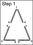
Step 1. After removing the rear end bell of the motor, the delta can be identified by the end of each phase connected to the start of another phase, forming the delta. The ends are readily identified, being joined at motor leads #1, #2, and #3.
Step 2. After the delta is identified, the two windings of each joint should be separated. The ends of all 9 motor leads should also be separated so that no two ends are touching (for testing purposes). Care must be exercised when more than one circuit winding is being used. Each phase winding must be separated as illustrated in Step 2. The three motor leads forming the delta will have twice as many ends joined as the other six motor leads; i.e., a one circuit delta will have two ends joined to lead #1; whereas a two circuit delta will have four ends joined at lead #1.
By using an ohmmeter or test light, lead #1 will show continuity with lead #4, and the end or ends disconnected from lead #1 will show continuity with lead #9. A length of lead wire should be attached to this and marked #12. You will find that #2 will show continuity with lead #5 and the end or ends disconnected from lead #2 will show continuity with lead #7. A lead wire should be attached and marked lead #10. Lead #3 will show continuity with lead #6 and the end or ends disconnected from #3 will show continuity with lead #8. A lead wire should be attached and marked lead #11.
The three additional leads are brought out into the motor connection box resulting in a total of 12 leads emerging from the motor winding. With the motor modified per the above procedure, it may now be used with a 460 Volt H-A-S Static Converter only. See page 3 for connections.

