INDIVIDUAL MOTOR CORRECTION
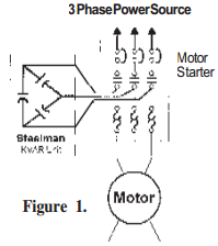
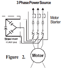
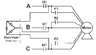
Figure 1 is the preferred connection to use when possible. If Figure 2 is used, the overload relay heater coils must be resized.
Caution: Do not oversize power factor correction capacitors. Do not connect KVAR units to the load side of a starter or contactor for motors subject to reversing, plugging, or frequent starts; crane or elevator motors, or any motor where the load may drive the motor, or multispeed motors, or motors involving open transition reduced voltage starting. On these applications, the KVAR units should be installed on the distribution system ahead of the motor controller, and must not be switched with the load motor.
DISTRIBUTION PANEL
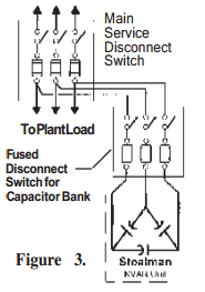
Caution: Applying large fixed KVAR units on the main service can cause a leading power factor when plant loads vary widely. The capacitors should only be on line when the load requires KVAR and disconnected when the load is reduced.
SPECIAL MOTOR APPLICATIONS
The diagrams below show capacitor connections for typical starting circuits for reduced voltage motor controllers. Make sure that the circuit matches the actual motor diagram before applying capacitors. Improper connection may result in damage to the motor and capacitors. The capacitors should be connected on the load side of the main contacts as shown.
AUTOTRANSFORMER
PART – WINDING
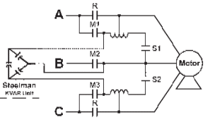
SERIES RESISTANCE
WYE – DELTA
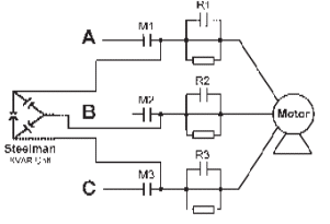
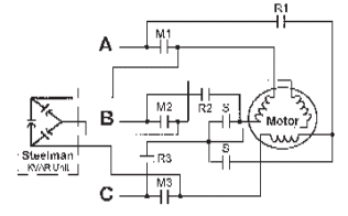
Figure 4

